The APOGEE Northern and Southern Spectrographs
APOGEE-1 and APOGEE-2 constituted a high-resolution, near-infrared spectroscopic survey of several hundred thousand stars in the Milky Way Galaxy. Spectra are observed with custom-built, multi-object spectrographs, which record the spectra of 300 targets simultaneously across the H-band wavelength regime with an approximate resolution of 22,500. The APOGEE spectrographs are now used by the Milky Way Mapper.
The first APOGEE spectrograph was constructed and assembled primarily at the University of Virginia. It is situated at the 2.5-m Sloan Foundation Telescope at Apache Point Observatory and was commissioned in August 2011 during the SDSS-III APOGEE-1 Survey period. The second APOGEE spectrograph had a similar build process and is almost analogous to the first. It is located at the 2.5-m Irenee du Pont Telescope at Las Campanas Observatory and was commissioned two and half years into the SDSS-IV APOGEE-2 Survey, during February and March of 2017.
For the set-up of both the Northern and Southern instruments, light is transmitted from the telescope focal plane to the pseudo-slit within the cryogenically cooled instrument via 300 low-OH (“dry”) fused silica fibers which have a 2″(N)/1.3″(S) field of view on the sky. Each of the 300 fiber runs consist of two fiber assemblies connected in series. A 2-m fiber run (so-called “fiber harness”) goes from the plug plate to a “gang-connector” just below the telescope and plug plate cartridge. Multiple cartridges are used throughout the night to observe different parts of the sky and each cartridge has its own set of 300 fiber harnesses. An innovative gang-connector allows the simultaneous connection of all 300 fibers from a specific cartridge to the single fiber run (“fiber link”) that transmits the light from the telescope and cartridges into the APOGEE spectrograph. To avoid throughput losses from the use of another fiber coupling, the fibers are fed through an epoxy-sealed vacuum feed-through without a break at the cryostat wall. Lastly, fibers that make up the fiber link terminate at the instrument pseudo-slit that is inside of the cryogenically cooled instrument.
An ‘uncorrected’ Schmidt camera, used in reverse, collimates the light of each of the fibers. The fiber tips are carefully positioned on a curved pseudo-slit. The pseudo-slit and spherical collimator have a common center of curvature near the system pupil which is also the approximate position of the spectrograph grating. The design is on-axis so the pseudo-slit is an obscuration in the collimated beam. Two-fold mirrors are used for efficient packaging of the optics train within the cryostat.
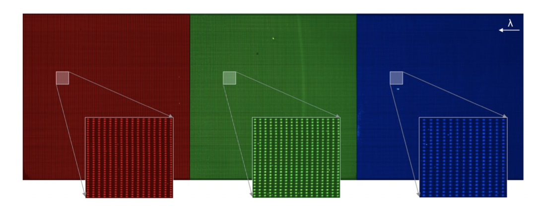
The dispersive optic is a transmissive 3-panel mosaic Volume Phase Holographic (VPH) grating fabricated by Kaiser Optical Systems Inc., the first-ever of its kind deployed in a cryogenic astronomical instrument (note for the Southern instrument, there is a slight departure in that the VPH is 2-panel). Due to its size, the grating area of the VPH was recorded in multiple steps (panels) and then processed and capped as a single unit. A 6-element refractive camera fabricated by New England Optical Systems focuses the various wavelengths of light onto the detectors. The camera is composed of mono-crystalline silicon and fused silica elements, the largest of which are nearly 400 mm diameter. Three JWST H2RG near-infrared detectors, on-loan from the University of Arizona, are mounted side-by-side to record the blue, middle and red portions of the spectrum. An Astronomical Research Camera (so-called Leach) controller operates all three detectors in sample-up-the-ramp mode.
While the nominal full-width half-maximum is approx. 2.3 pixels wide, the blue end of the spectrum is sampled with less than 2 pixels. To recover optimal sampling, the detector mount is translated (spectrally dithered) between sets of frames with a custom, precision single-axis actuator. For further details regarding the APOGEE spectrographs, users should consult Wilson et al. (2019).
Upgrades for the APOGEE instruments in SDSS-V
In 2021, the APOGEE instruments were both upgraded to improve both observing efficiency and radial velocity stability. The first upgrade will be replacing the focal plane plate and cartridge setup with a Robotic Focal Plane System (FPS).
The second major set of upgrades are designed to improve the radial velocity (RV) stability of the APOGEE instruments. The current RV floor is approximately 100 m/s. In SDSS-V, we are going to implement three hardware changes. The first is a Fabry-Perot Interferometer (FPI), which is a precise calibration lamp that will allows us to track minute changes in APOGEE instruments over time. The second is that octagonal fibers will be put into the FPS system. Octagonal fibers are much better at scrambling the incoming starlight producing a more repeatable point-spread function. The final improvement is adding a back-pressure regulator (BPR). The BPR will better isolate the spectrograph from external pressure variations. These three hardware improvements will allow us to improve the RV precision of the APOGEE instrument by a factor of three, down to a 30 m/s precision floor.
Highlights
General Characteristics of the Northern and Southern Spectrographs
- Spectral resolution
- 22,500 (approx.)
- Wavelength coverage
- 1.51 – 1.70 μm
- Fiber diameter
- 2 arcsec (Northern Spectrograph), 1.31 arcsec (Southern Spectrograph)
- Throughput
- ~15% H broad-band efficiency (including atmosphere)
- Sensitivity
- S/N~100/pixel for H < 12.2 and 3-hour integration
- Detectors
- Three JWST H2RG (2048 x 2048) Near-Infrared HgCdTe Detectors with 18 micron pixels
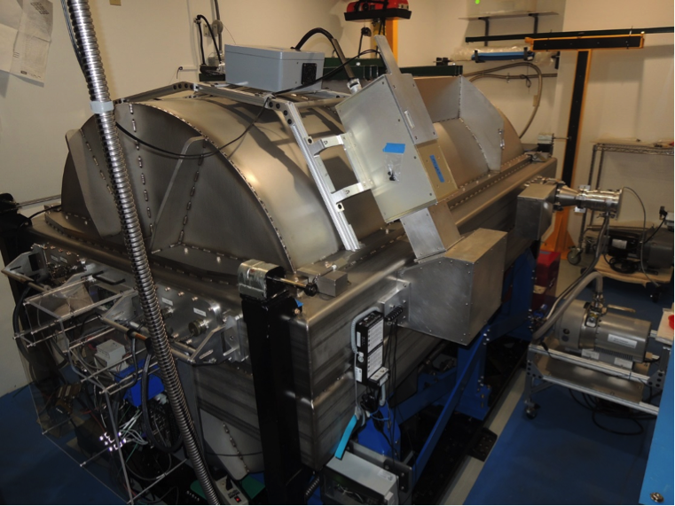
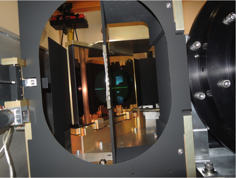
Photos
Northern instrument
Southern instrument