Explore below to learn more about the SDSS telescopes, the SDSS spectrographs, and the SDSS imager.
Telescopes
The Sloan Foundation 2.5m Telescope at Apache Point Observatory
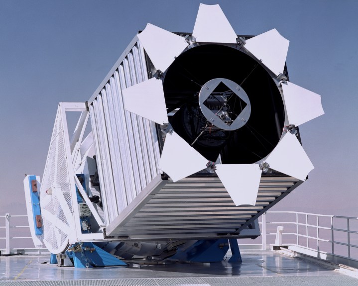
The SDSS uses a dedicated 2.5-m f/5 modified Ritchey-Chrétien altitude-azimuth telescope located at Apache Point Observatory, in south east New Mexico (Latitude 32° 46′ 49.30″ N, Longitude 105° 49′ 13.50″ W, Elevation 2788m). A 1.08 m secondary mirror and two corrector lenses result in a 3° distortion-free field of view. The telescope is described in detail in a paper by Gunn et al. (2006).
The Irénée du Pont Telescope at Las Campanas Observatory
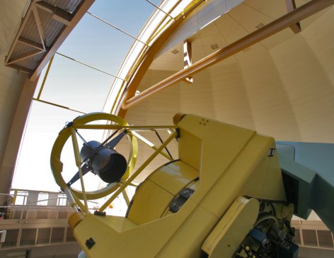
The fourth phase of the SDSS included its first observations obtained from the Southern Hemisphere. The southern observations are taken with the Irénée du Pont Telescope at Las Campanas Observatory in northern Chile (Latitude 29° 0′ 52.56″ S, Longitude 70° 41′ 33.36″ W, Elevation 2380m). The du Pont telescope is a Ritchey-Chrétien 2.5-m f/7.5 telescope with a Gascoigne corrector lens. The telescope is described in detail in a paper by Bowen & Vaughan (1973).
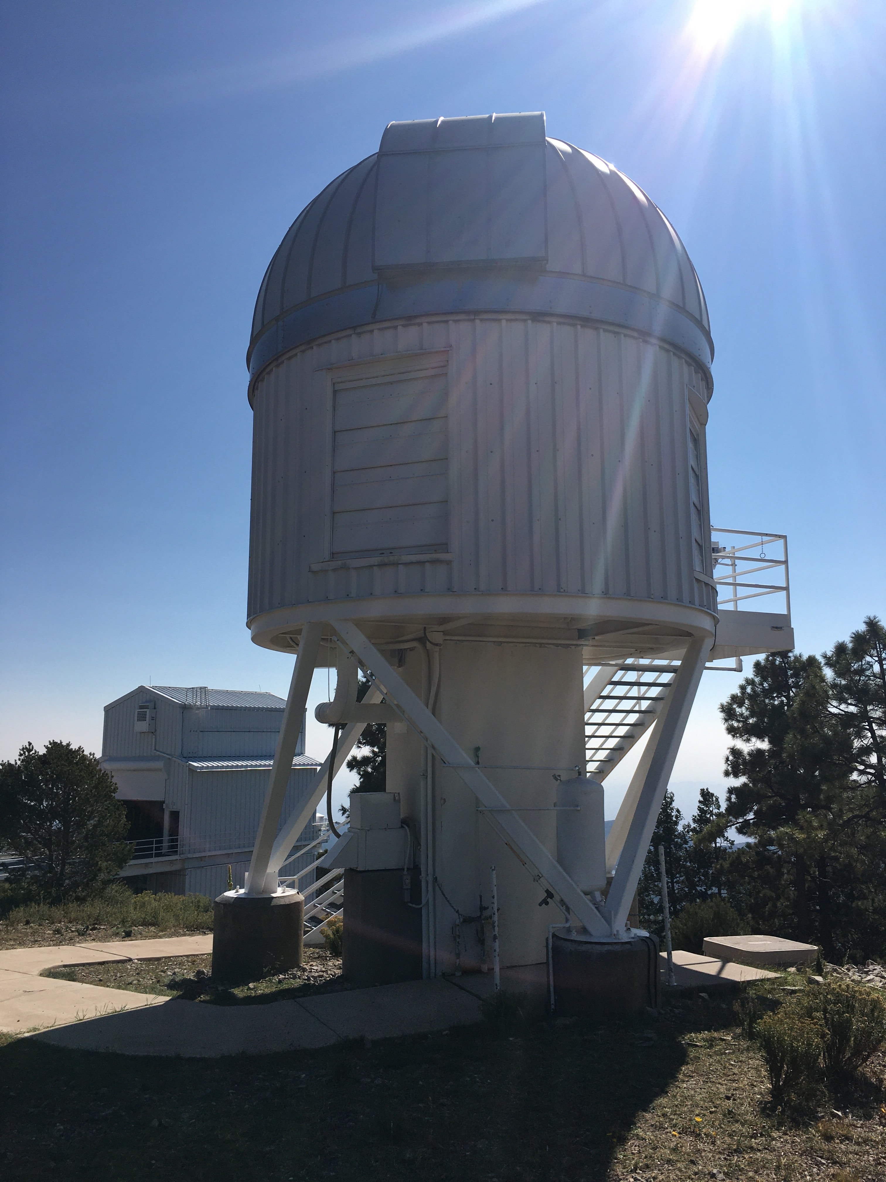
Local Volume Mapper Enclosure
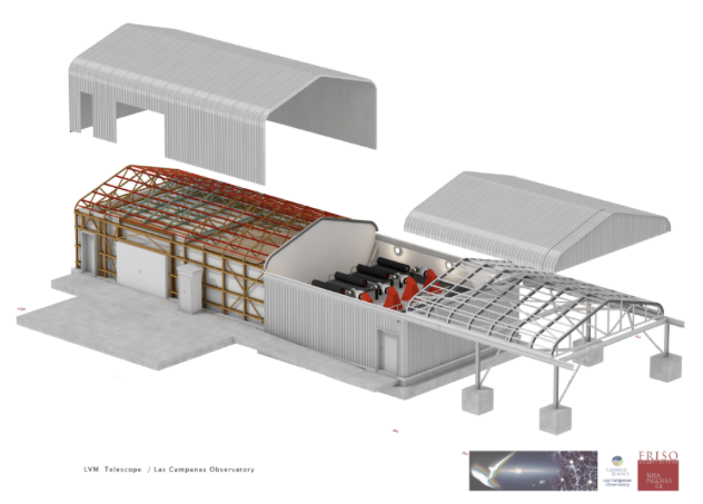
The Local Volume Mapper uses an innovative system of four 0.16 m telescopes coupled with an extremely powerful fiber-fed integral field spectrograph housed in an environmentally controlled clean laboratory. The Local Volume Mapper Instrument (LVM-I) is hosted in a stand alone facility at Las Campanas Observatory in Chile.
Spectrographs
BOSS spectrographs
SDSS-V continues to use the spectrographs originally built for BOSS. These two identical spectrographs are rebuilt from the original SDSS spectrographs, which were used for the SDSS Legacy and SEGUE surveys. Each spectrograph has two cameras, one red and one blue, with a dichroic splitting the light at roughly 6000 Å and a full wavelength range from 3600 to 10,400 Å. Additional information can be found on the BOSS spectrograph page.
APOGEE spectrographs
The APOGEE spectrographs are high-resolution, near-infrared spectrographs originally built for the APOGEE surveys. The instruments are custom-built, multi-object spectrographs that record the 1.51-1.70 micron spectrum of 300 targets simultaneously, with a spectral resolution of ~22,500. Additional information can be found on the APOGEE spectrographs page.
Local Volume Mapper instruments
The Local Volume Mapper Instrument (LVM-I) is using a new facility built for the LVM Survey. A custom building, four 16-cm telescopes, integral-field unit, and fiber slit feed near-clones of the R~4,000 DESI spectrograph. In a single shot these produce ~1,800 spectra from 3600 to 9500 Angstrom. Additional information can be found on the LVM-I page.
Robots
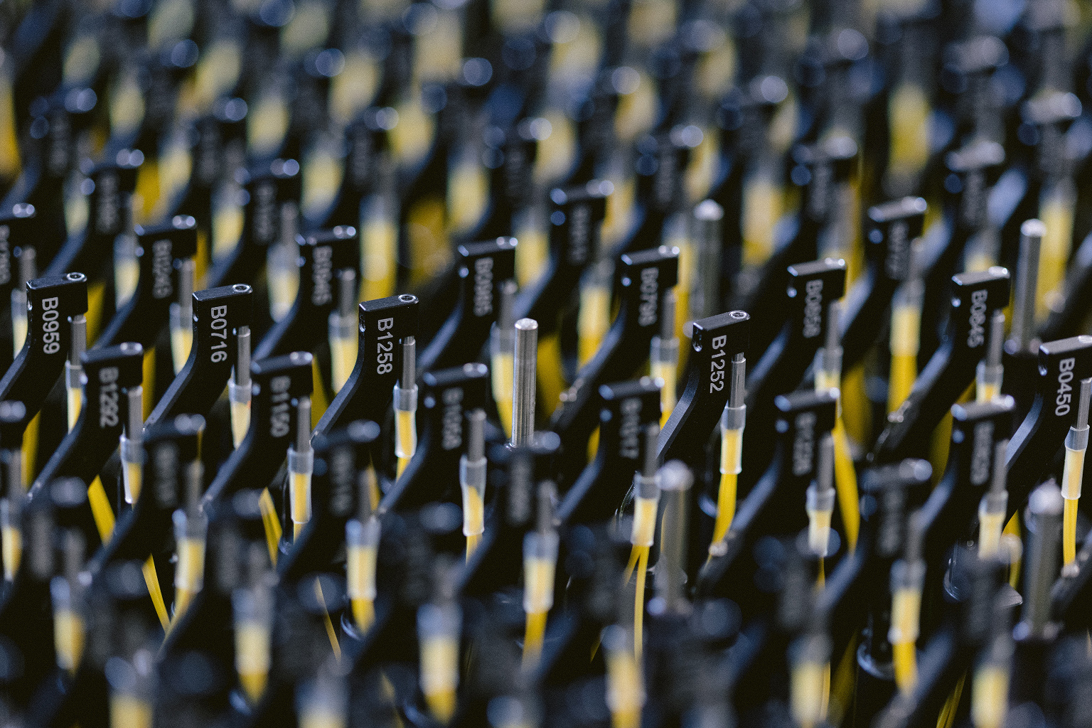
Robotic Focal Plane System (FPS)
To meet the requirements for SDSS-V’s rapid cadence and high target densities, we replaced the iconic SDSS fiber plug-plates on both telescopes with robotic Focal Plane Systems (FPS). Each FPS deploys 500 robotic fiber positioners. 300 robots carry fibers for the BOSS and APOGEE spectrograph plus a back-illuminated metrology fiber, and 200 carry a BOSS fiber and a metrology fiber. A telescope-mounted fiber viewing camera system is used to ensure precise fiber positioning. The robot array is surrounded by six guide/focus/acquire (GFA) cameras to provide precise acquisition, guiding, and telescope focus maintenance. Additional information can be found on the Focal Plane System page.
The retired SDSS camera
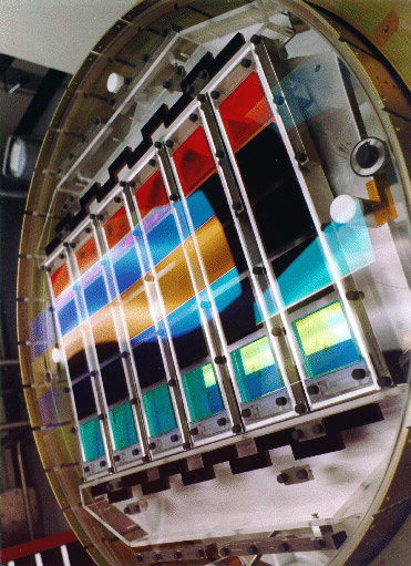
The SDSS’s imaging camera is now at the Smithsonian, but all the images it collected are available online. The imaging camera collected photometric imaging data using an array of 30 SITe/Tektronix 2048 by 2048 pixel CCDs arranged in six columns of five CCDs each, aligned with the pixel columns of the CCDs themselves. SDSS r, i, u, z, and g filters cover the respective rows of the array, in that order. The survey operated the instrument in a drift scan mode: the camera slowly reads the CCDs while the telescope moves along great circles on the sky so that images of objects move along the columns of the CCDs at the same rate the CCDs are being read. As an image of an object moves along the column of the CCDs, a CCD in each row collects data on that object. Therefore, the camera produces five images of a given object, all from the same column of CCDs, one from each CCD in that column. It takes an object 54 seconds to move from the beginning of a CCD to the end, so the effective exposure time in each filter is 54 seconds. Because there is some space between the rows of CCDs, it takes an image 71.7 seconds to move from the beginning of one row to the next. Each row corresponds to a different filter, so each object has one image in each filter, taken at 71.7 second intervals. A detailed description of the imager can be found in Gunn et al. (1998) and in the SDSS-I project book. Additional information can be found on the Camera page.
Retired Spectrographs
MaNGA
MaNGA is a galaxy survey which is obtaining detailed integral field unit (IFU) resolved spectroscopy measurements of 10,000 nearby galaxies. MaNGA uses the eBOSS / BOSS spectrograph, but instead of placing a single fiber on each galaxy, it uses specially-designed hexagonal ferrulesto close-pack the circular fibers into hexagonal bundles. Each MaNGA cartridge contains 17 bundles ranging in size from 19 to 127 fibers, each enabling detailed observations of 17 galaxies simultaneously. Additional Information can be found on the MaNGA fiber feed page.
MARVELS
MARVELS used a specially-built interferometric spectrograph to obtain high-precision radial velocity measurements of stars looking for exoplanet candidates. In contrast to the more traditional high-resolution echelle spectrographs, MARVELS used a new approach to measuring radial velocities. The spectrograph is a fiber-fed dispersed fixed-delay interferometer (DFDI), a combination of Michelson interferometer and a medium resolution (R~6,000-10,000) spectrograph, which overlays interferometer fringes on a long-slit stellar spectrum. Additional Information can be found on the MARVELS spectrograph page.
SDSS-I/-II spectrograph
The SDSS-I/-II used two spectrographs, each of which had a blue channel and a red channel separated by a dichroic filter. 640 fibers (320 fibers per spectrograph) feed light from the focal plane into the spectrographs. A total of four 2048 × 2048, SITe/Tektronix CCDs (one for each channel of each spectrograph) collect the spectra. SDSS-I/-II Spectrograph page.
Previous Telescopes
The NMSU 1-Meter Telescope at Apache Point Observatory
A number of important stars that are too bright to observe with the larger telescopes were instead observed for APOGEE with the NMSU 1-meter telescope at APO (Latitude 32° 46′ 49.30″ N, Longitude 105° 49′ 13.50″ W, Elevation 2788m). A fiber lead connected the APOGEE-North spectrograph to this facility, which contained a Ritchey-Chretien reflector set on an alt-azimuth mount. The details of this telescope can be found in Holtzman et al. (2010). It is not currently used for SDSS-V observations.