Introduction
To reach our science goals in SDSS given observing constraints and limited telescope time, we need to select the specific set of targets that would be eligible for observations. These targets are taken from a very large list of stars and galaxies previously observed by single or multiple external catalogues (complemented with our own SDSS catalogues). Then, each of our science programs (see BHM Programs and MWM Programs) selects one or multiple subgroups of targets called cartons, which can partially overlap with targets from other cartons.
In the “plate-era” of SDSS, we used aluminum plates with holes drilled in specific locations to place the the fibers that would capture the light from each target for a given observation. For each observing run plates had to be drilled and shipped to the mountain in advance, which implies that the list of targets to be observed with each plate from that run had to be derived with months in advance. On the other hand, in the “FPS-era”, we use a Focal Plane System (FPS) where a set of robots place the fibers corresponding to each target for every observation. Unlike plates, in the FPS configuration robots can quickly change the combination of fiber positions without the restriction of having to place the fibers in specific pre-defined locations as is the case for plate-holes in the plate system. This means that FPS enables us to make observations in a considerably shorter time baseline that was not possible with plates. How targets from cartons are assigned to plates and FPS observations is explained in sections Plates and FPS webpages respectively.
Database Tables Creation
To efficiently store our data and make it easily accessible for analysis we use a PostgreSQL database with multiple schemas. As the figure below shows, database loading starts with a set of internal (SDSS) and external catalogues, that are crossmatched and combined into the catalog table.
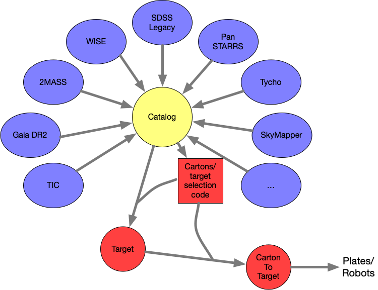
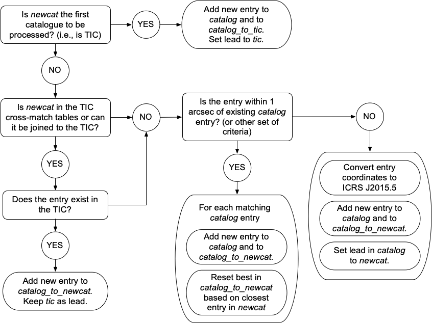
The crossmatch happens in three phases, phase1 where we link tables through external ids contained in tables, phase2 where we do a spatial crossmatch using coordinates and proper motions, and phase3 where we ingest the entries that haven’t been crossmatch. Tables are ingested in order, and each entry from for example tableN that is ingested in phase3 is added to the catalog table with a unique identifier called “catalogid” and with parameter lead=tableN, which means that the coordinates, proper motions, and parallax value (if available) are taken from tableN. An entry is also added to a table that in this case would be called catalog_to_tableN, a table that is created to relate stars in a specific table to their counterparts in the catalog table. In phases 1 and 2 stars are matched to entries already present in table catalog, and for example if a star from tableM is linked in phase1 or spatially matched in phase2 to a star in the catalog table, then an entry is added to the table catalog_to_tableM. To check more details on how the crossmatch phases work for each table that is ingested please see the figure below.
After the catalog table, and the catalog_to_tablename tables are created we can use those tables to relate the entries from the different input tables. Then, each carton defines a selection algorithm that use these tables and the input tables to produce their list of targets for the carton. Every star from the catalog table (every catalogid) that is selected in one or multiple cartons is added to the “target” table where we include the “catalogid” value (identifier in the catalog table), the coordinates and the proper motions. Then, table carton_to_target table contains all the entries selected from all the cartons, where we include information useful for observation assignment like the cadence and the priorities, along with the “target_pk” parameter which is the “pk” identifier in the target table, and the “carton_pk” parameter which is the “pk” identifier in the carton table. Since a given target (catalogid in catalog) can be selected in multiple cartons, a single “target_pk” in the target table can have multiple counterparts in the carton_to_target table. Finally, the “carton” table contains the list of cartons from bhm and mwm, where we indicate the mapper, the name of the carton and the program to which the carton belongs. After all these tables have been created, table carton_to_target is then used to assign targets for observation.
Targeting Content
Selection algorithms for carton creation are defined according to the scientific goals defined for the science programs to which the carton belongs. To see the description of the Milky Way Mapper and Black Hole Mapper programs please visit (BHM Programs and MWM Programs).
The full list of cartons included in this data release is attached here as text file and as csv.
In the following table we show a few example rows of the tables linked above.
| carton | program | carton_ pk | target_ selection_ plan | mapper | category |
|---|---|---|---|---|---|
| bhm_aqmes_med | bhm_aqmes | 731 | 0.5.0 | BHM | science |
| bhm_csc_apogee | bhm_csc | 1115 | 0.5.15 | BHM | science |
| bhm_gua_dark | bhm_filler | 711 | 0.5.0 | BHM | science |
| … | … | … | … | … | … |
| … | … | … | … | … | … |
| manual_mwm_tess_ob | mwm_tessob | 1134 | 0.5.13 | MWM | science |
| openfibertargets_nov2020_11 | open_fiber | 1003 | 0.5.3 | science | |
| ops_sky_apogee_best | ops_sky | 1097 | 0.5.9 | sky_apogee | |
| ops_std_eboss | ops_std | 529 | 0.5.0 | standard_boss | |
In the table presented above the program column indicates the mapper along with the scientific program name for regular cartons; “open_fiber” for programs the come from a call to fill fiber exposures that are not assigned to any of the stars in the core programs of MWM and BHM; and programs with prefix “ops” are operation sky and telluric standard for the APOGEE and BOSS instrument. The carton_pk column is a unique identifier for the carton, and each combination of carton/target_selection_plan has a different carton_pk value. The target_selection_plan column tracks the different versions of the cartons, each time a set of carton target selection algorithms change we flag it with a plan value that has a one-to-one relation with the tag of the code. The mapper indicates if it is a Milky Way Mapper or Black Hole Mapper Carton, and it is empty when is not associated with any of them. Finally the category column can be “science” for science cartons, and “sky” or “standard” followed by the instrument for calibrations cartons.
Details and motivation of the different cartons can be found in MWM cartons and BHM cartons.
Target Selection
After the database has been created and the different teams have created the cartons with specific science goals, we need to assign targets from these cartons for observations. The method used to assign targets in the plate-era and FPS-era of SDSS-V is explained in the child pages Plates and FPS.